

How can we help you?

How can we help you?

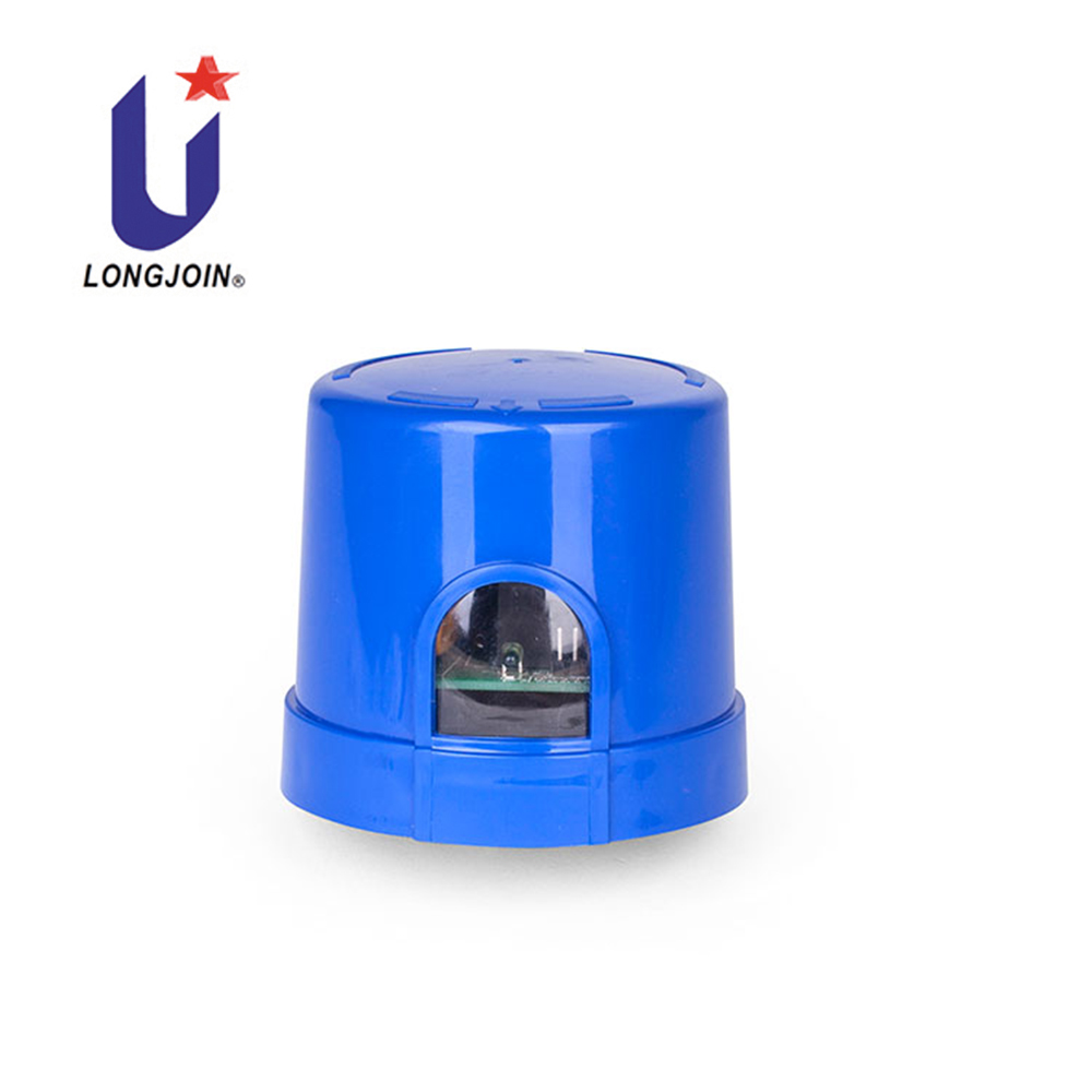
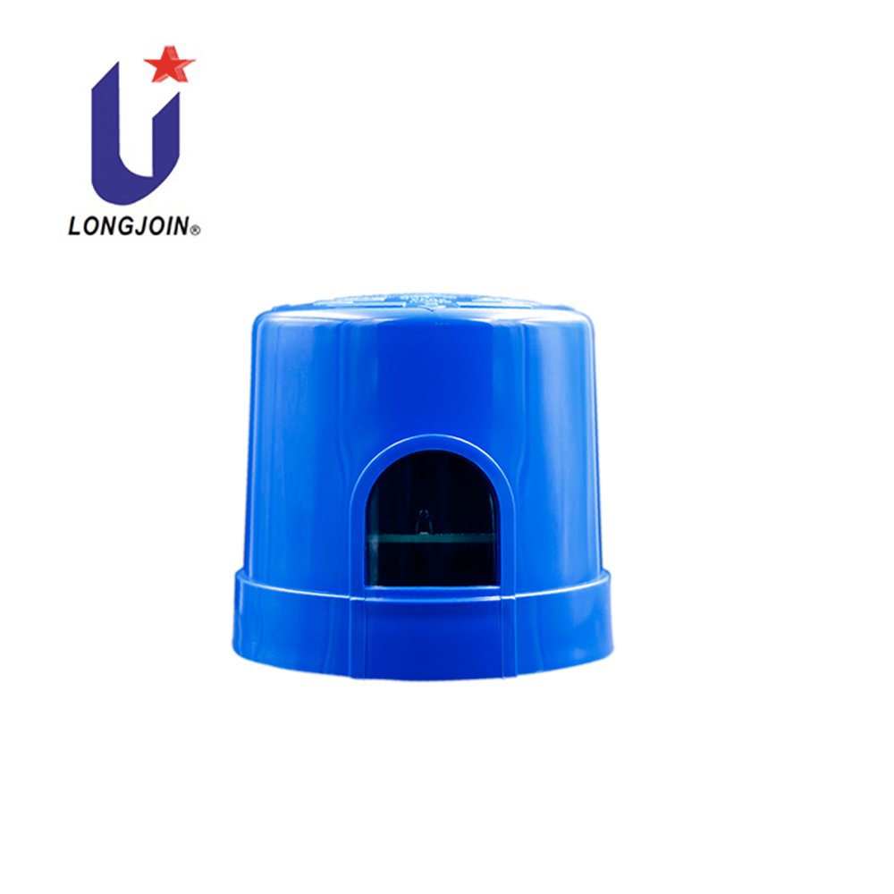

The outdoor photocell light switch sensor JL-254 series is applicable to control any independent LED home/street lighting with 0-10V automatically in accordance with the ambient natural lighting level, as well as remote control by using a gateway box (JL-254P or JL-254V) connected to a smart phone either iOS and Andriod OS with Bluetooth communication, while connected to the smart control (JL-254C) with Zigbee communication.
This smart control JL-254C is designed with microprocessor circuits with IR-filtered silicone sensor, a heavy duty surge arrester (MOV) 40kA is provided to protect the lamp from inrush current as well as impulse by lightening.
Further, a preset 3-5 seconds time-delay prevents excessive operation due to spotlight or lightning during the night time. A heavy duty relay supports the work life of over 15,000 cycles,.
This smart control JL-254C provides twist lock terminals and signal contacts, in 7P, meeting the requirements of ANSI C136.41-2013, as well as being listed by UL under the Standard for Plug-In, Locking Type Photo control for Use with Area Lighting ANSI/UL773.
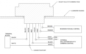
Disconnect power; wire the color coded receptacle according to the diagram below.
Push the photocontroller on and twist it clockwise to lock it into the receptacle.
Install the photocontroller with the Photocell facing the NORTH direction as indicated on the top of the photocontroller.
Adjust the receptacle position if necessary.
It is normal for the SWITCH to take several minutes to turn off when first installed.
To test “turn on” during daytime, cover its eye with sliding the metal strip mounted.
Do not cover with finger because light traveling through fingers may be great enough to keep the switch open.
Test will take approximately 2 minutes.


Copyright Longjoin Electronics Co., Ltd. Shanghai 2008. All Rights Reserved
沪ICP备2022000883号-1

