

How can we help you?

How can we help you?

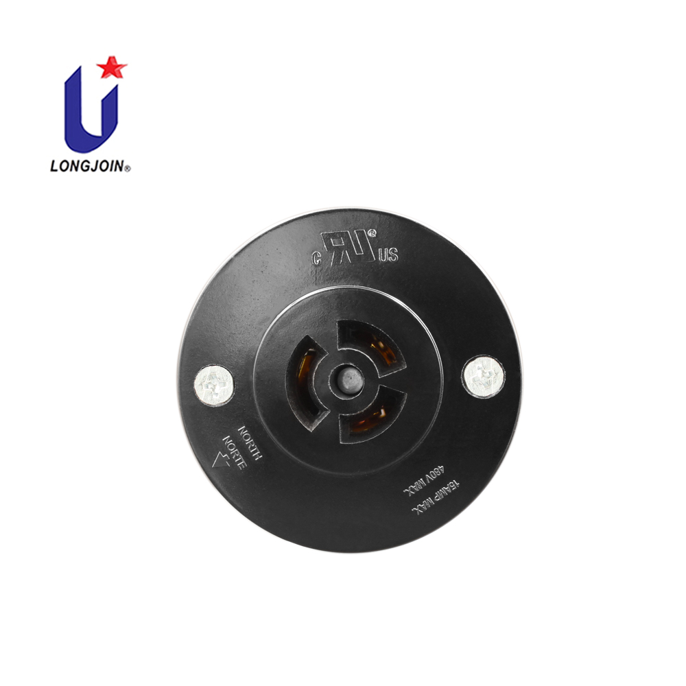
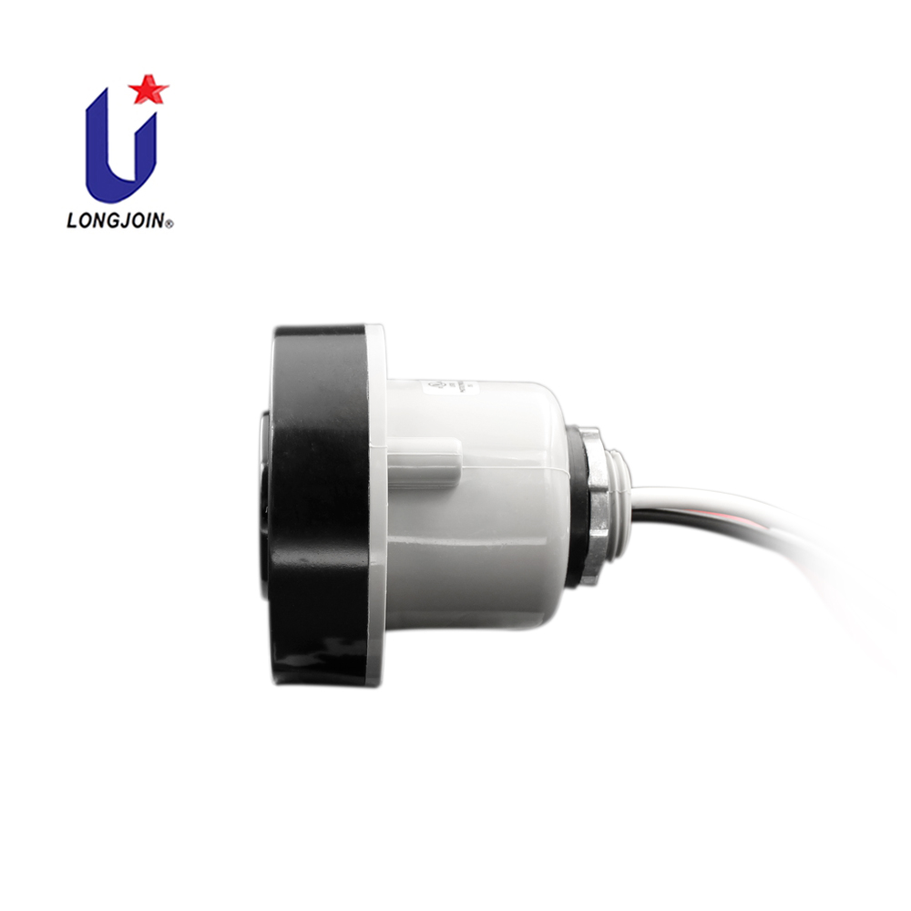

All the JL-200 Series Photocontrol Receptacles were Designed for the Lanterns those without an ANSI C136.10-1996 Receptacle Equipped to fit a Twist-lock Photocontrol.
Both JL-200-14 and JL-200Z14 have been listed, and JL-200X14 has been recognized by UL to applicable US and Canadian safety standards, under their file E188110, Vol.1 & Vol.2.
-Product Diagram-

-Product Parameters-
| Model No. | JL-200Z | |
| Applicable Volt Range | 0~480VAC | |
| Rated Frequency | 50/60Hz | |
| Suggested Loading | AWG#18: 10Amp; AWG#14: 15Amp | |
| Ambient Temperature | -40℃ ~ +70℃ | |
| Related Humidity | 99% | |
| Overall Dimensions (mm) | 65Dia.x65 | |
| Accessory | Back/Front Cover | |
Zinc Alloy Lock Nut | ||
Mounting Plate/Base | ||
| Leads | 6” Min. | |
| Weight Approx. | 135g | |

Disconnect power; wire the Photocell Socket according
to the Diagram in right hand. An arrow indicating
NORTH on the top of the Receptacle is used to
assist correct direction. Push the Photocontroller
on and Twist it Clockwise to lock it into the Photocell
Receptacle.
Install the Photocontroller with the Photocell
facing the NORTH direction as indicated on
the top of the Photocontroller.
Adjust the receptacle position if necessary.


Copyright Longjoin Electronics Co., Ltd. Shanghai 2008. All Rights Reserved
沪ICP备2022000883号-1

