How can we help you?

How can we help you?


Product introduction
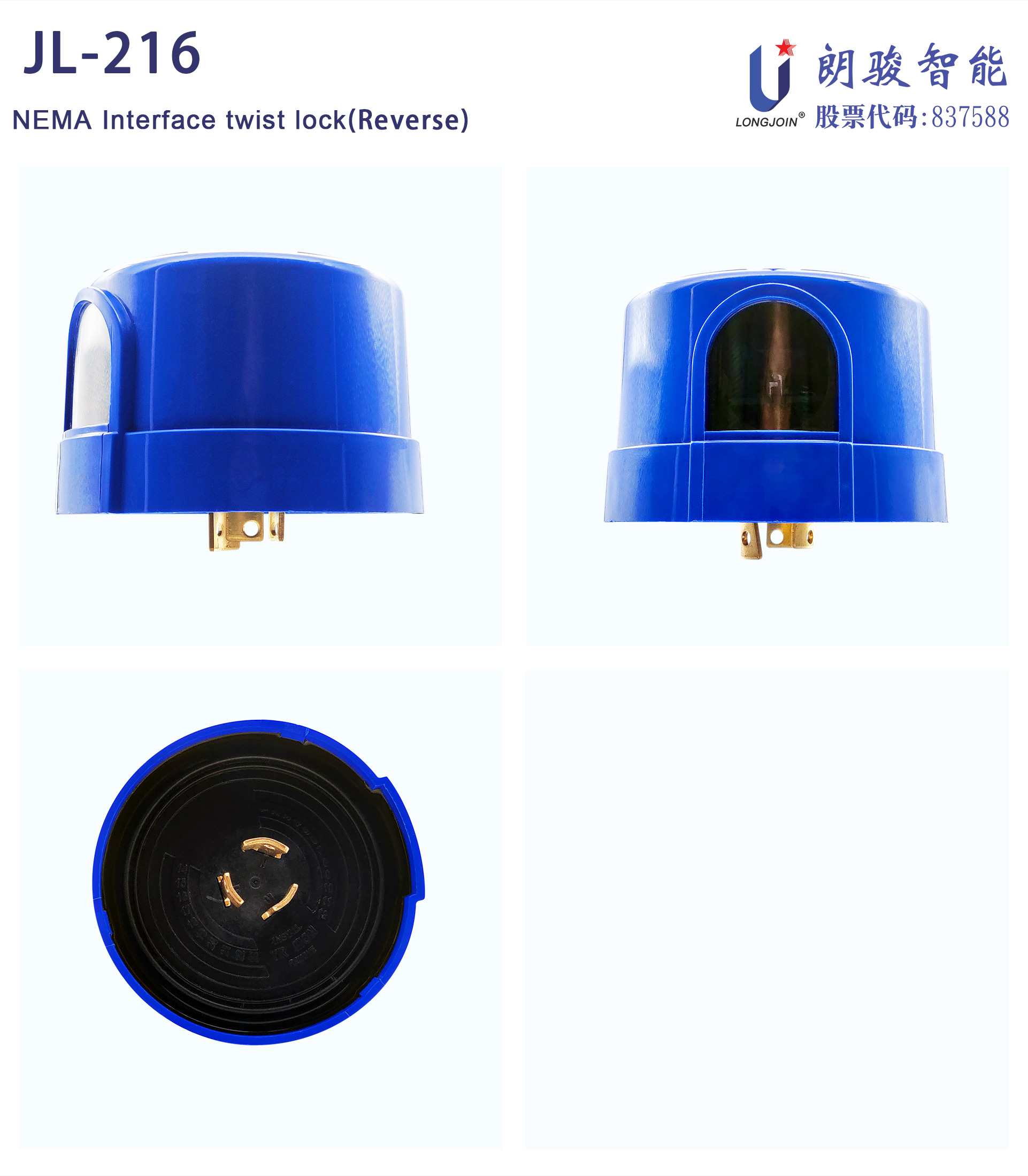
JL-216 twist lock analog electronic light control switch series products are applicable to independently control street lighting, garden lighting, passage lighting, porch lighting and park lighting according to the ambient natural lighting level.
This series of products has designed a microprocessor circuit with infrared filter optical transistor and is equipped with a surge arrester (MOV). In addition, the preset 5-20 second time delay control function can avoid redundant operation caused by spotlight or lightning at night.
In contrast, the long-life version can maintain constant and reliable characteristics. The relay can have more than 10000 working life cycles. When a double-layer protective shell is installed, it can provide a longer working life for JL-216.
This series of products provides three lock terminals, which meet the requirements of ANSI C136.10 and ANSI/UL773 standards for plug-in and rotary lock optical controllers for area lighting.


Product Features
·ANSI C136.10 twist-lock
·Wide voltage
·Inverse illuminance
·Fully customizable
·Built-in surge protection
·Infrared filter phototransistor
·Midnight light
·Zero crossing protection
·Optional failure mode on/off
· UV-resistant housing
·Support FCC class A
Parameter Lists
| Item | JL-216C | JL-216E | JL-216F | |
| Rated Voltage | 120-277VAC | 347VAC | 480VAC | |
| Rated Frequency | 50/60Hz | |||
| Work Temperature | -40℃-70℃ | |||
| Relative Humidity | 96% | |||
| Rated Loading | 1000W Tungsten;1800VA Ballast;8A@120VAC 5A@208-277VAC e-Ballast | 1000W Tungsten;1800VA Ballast;8A@120VAC 5A@ e-Ballast | 1000W Tungsten;1800VA Ballast; | |
| Power Consumption | 0.5W Max | |||
| Surge Arrest | 4KV/6KV/20KV | N/A | ||
| On/Off lux | 16lux on /24lux off/per client request | |||
| Fail Mode | C5:on C4:off | E5:on E4:off | F5:on F4:off | |
| Cross Zero | option | N/A | ||
| FCC | Optional | N/A | ||
| IP Rating | IP54/IP65/IP67 | |||
| double Cover | optional | |||
| Certificate | UL,CE,ROHS | |||
Installation Instructions
*Disconnect the power supply.
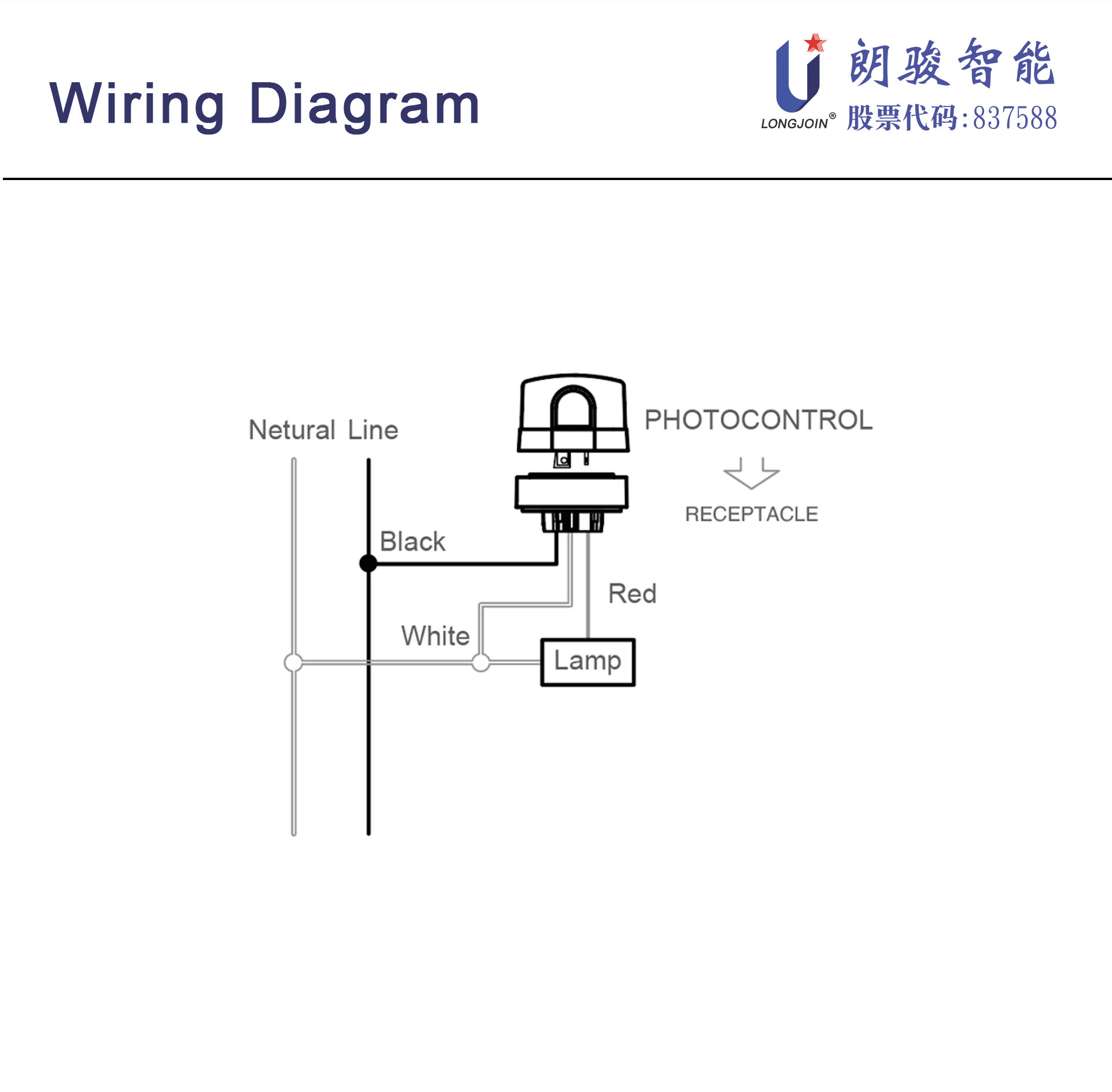
*Connect the socket according to the figure below.
*Push the photoelectric controller up and turn it clockwise to lock it in the socket.
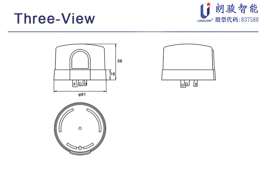
*If necessary, adjust the socket position to ensure that the light sensing port points to the north as shown in the triangle on the top of the light controller.

Initial testing
*When installing for the first time, it usually takes several minutes to close the optical controller.
*To test "open" in the daytime, cover the light-sensitive window with opaque material.
*Do not cover it with your fingers, because the light passing through your fingers may be enough to turn off the light control device.
*The light controller test takes about 2 minutes.
*The operation of the light controller is not affected by weather, humidity or temperature changes.

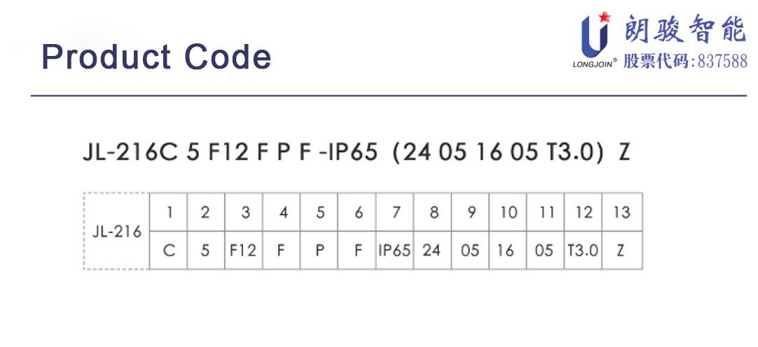
1: C = 120-277VAC
E = 347VAC
F = 480VAC
2: 5 = On
4 = Off
3: F12 = MOV, 110J/3500A
F15 = MOV, 235J/5000A
F23 = MOV, 460J/10000A
F25 = MOV, 546J/10000A
F40 = MOV, 640J/40000A
M4K = MOV, 4KV Surge
D6K = R/C, 6KV Surge
R2W = R/C, 20KV Surge
A2W = A/D, 20KV Surge
4: F = Complies with FCC electromagnetic interference specification, Class B
N = Not verified for FCC compliance
5: P = UV stabilized polypropylene
C = UV stabilized polycarbonate
K = PP inner shell + PC outer shell
6: F = Blue D = Green H = Black
K = Gray (optional)
7: IP65 = Elastomeric ring + silicone outer seal
IP54 = Electronic associated foam gasket ring
IP66 = Elastomeric ring + silicone inner and outer seal
IP67 = Silicone ring + silicone inner and outer seal (including copper pin)
8: Illuminance level when turned on
9: On delay (seconds)
10: Illuminance level when turned off
11: Off delay (seconds)
12: Midnight dimming optional (hours)
13: Z = Optional zero-crossing control technology + longer service life
N = None