How can we help you?

How can we help you?


JL-712A3 zhaga book-18 latch controller
Piece Interpretation Series
Jl-712A3 zhaga book-18 latch controller of JL-7 series.
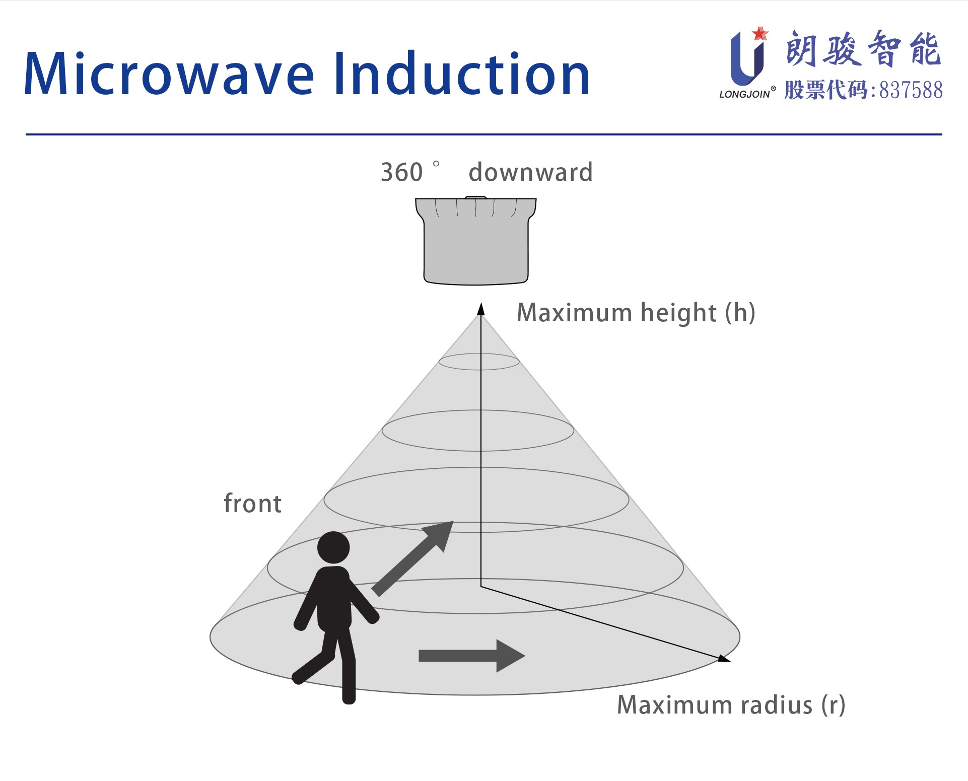
JL-712A3 is a latch type controller developed based on the interface size standard of zhaga book18. This product adopts a light sensor + microwave mobile combination sensor, which can output 0~10v dimming signal. The controller is suitable for lighting scenes such as roads, industrial mines, lawns, courtyards, parks, parking lots, industrial mines, etc.

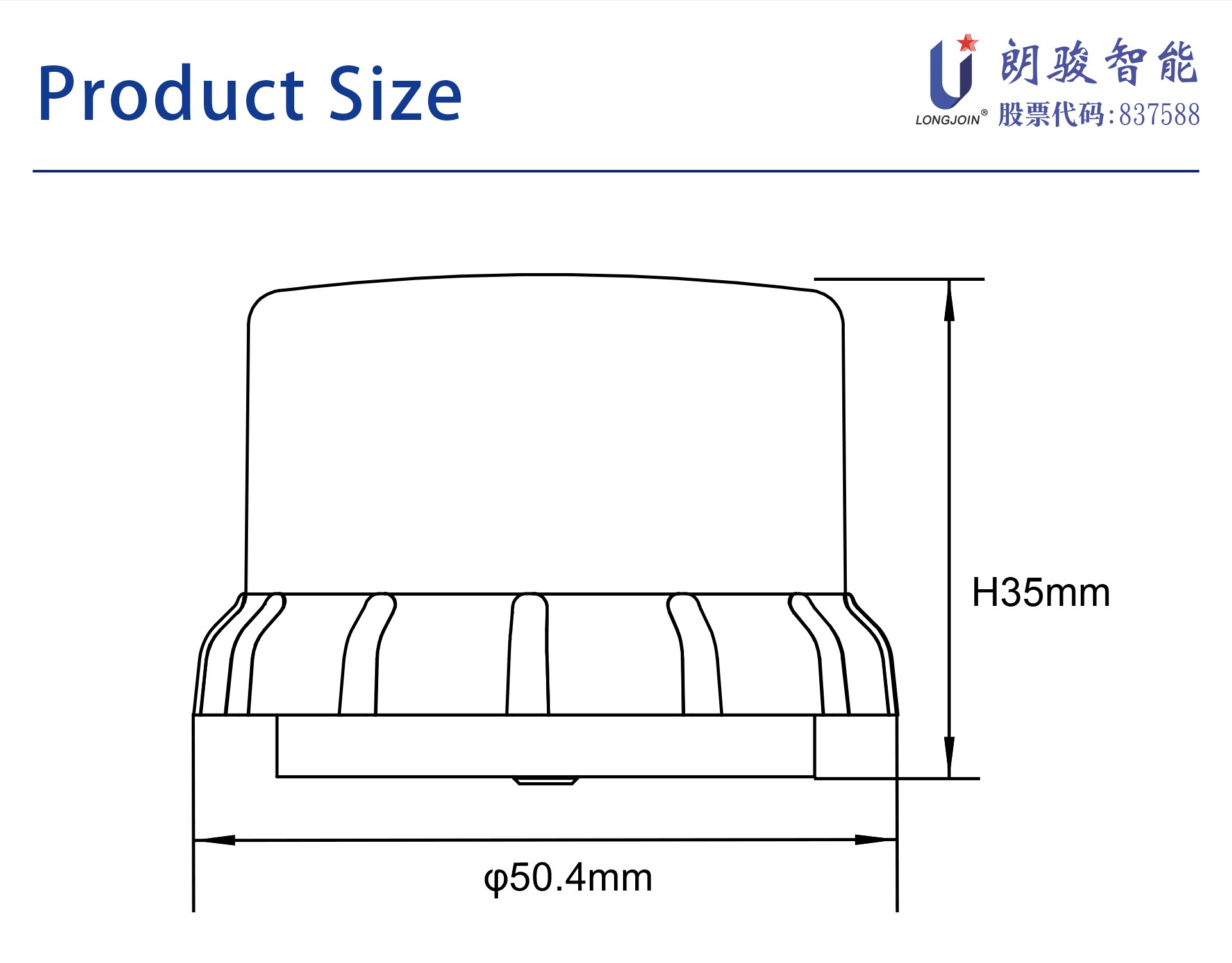
Product Dimension Drawing
Product Features
*Light sensor + microwave, lighting on demand, more user-friendly and more power-saving
* Microwave anti-false trigger, available indoors and outdoors
* Automatic dynamic microwave frequency adjustment to avoid interference between dense installations
* Compliant with Zhaga Book18 interface standard
* DC power supply, ultra-low power consumption
* Support 0~10V dimming mode
* Small size, suitable for installation in various lamps and lanterns
* Anti-false triggering design of interference light source
* Lamp reflected light compensation design
* Waterproof protection level up to IP66
Product parameters
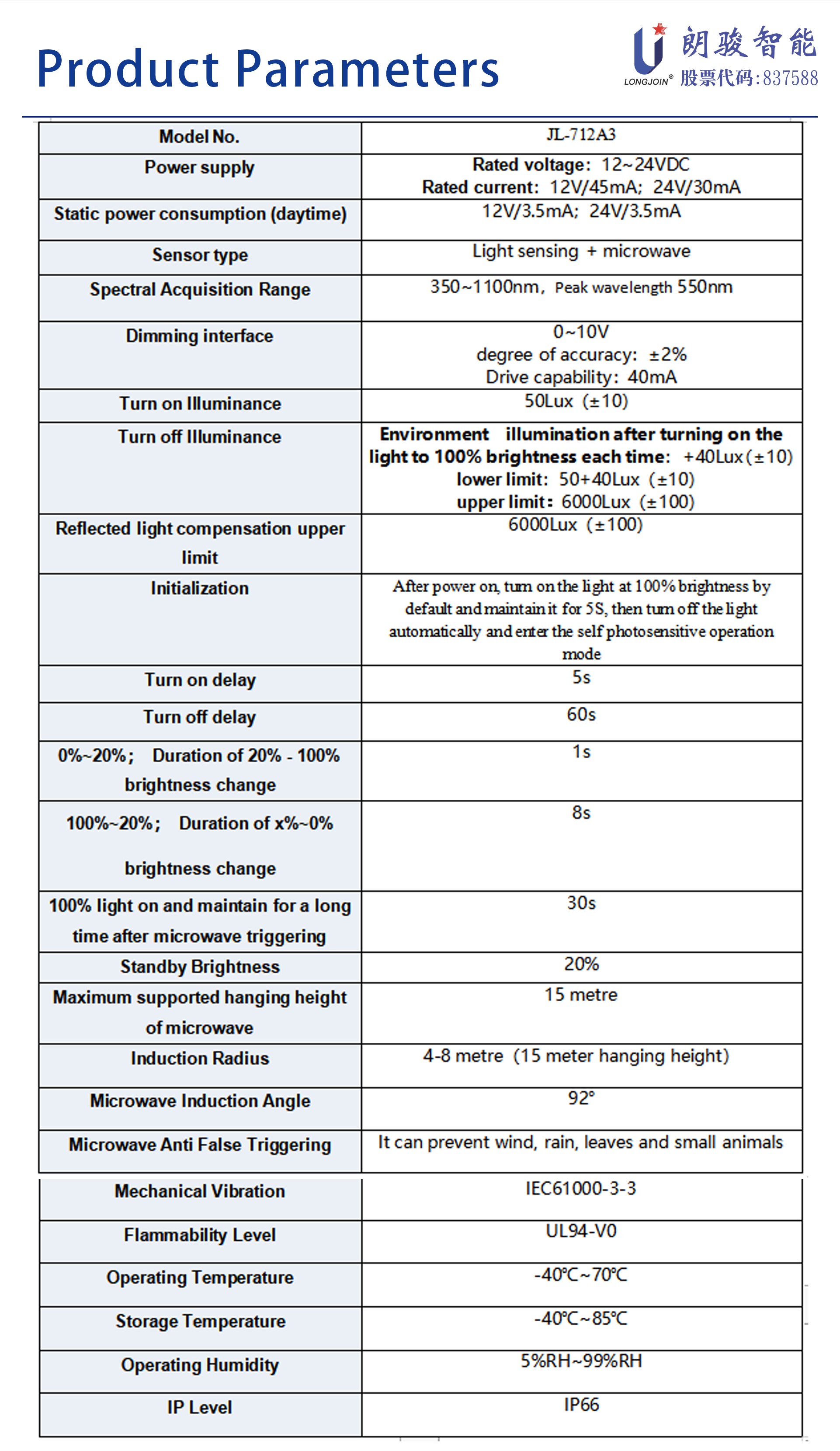
Remark:
*1: a. If the light-emitting surface of the lamp is completely shielded and isolated from the light-sensitive surface of the controller, that is, no reflected light enters the controller after the lamp is illuminated, then the light-off illuminance at this time is equal to the lower limit value, that is, the next time the light is turned off Light illuminance approximately = default light illuminance + 40lux compensation value = 50 + 40 = 90lux;
b. If the light-emitting surface of the lamp cannot be completely shielded and isolated from the light-sensitive surface of the lamp controller, that is, the reflected light enters the controller after the lamp emits light. If the lamp is lit to 100%, the current ambient illuminance collected by the controller is 500lux, then the next turn-off illumination is about = current ambient illumination + 40 = 540lux;
c. If the power of the lamp is high and the light-emitting surface and the light-sensitive surface of the controller are installed very close, the reflected light exceeds the upper limit of compensation after the lamp is lit to 100%, that is, the controller detects that the ambient illuminance after turning on the lamp has been stable and greater than 6000 lux, the controller will automatically turn off the lights after the 60s.
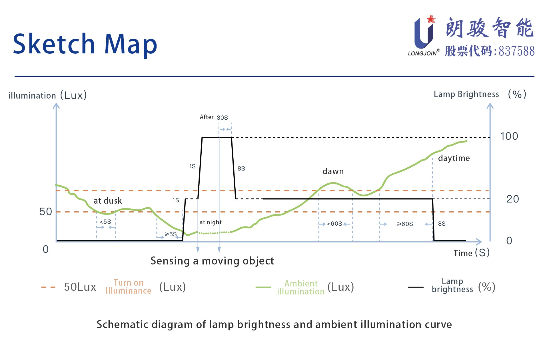
Schematic diagram of lamp brightness and ambient illuminance curve
Controller pin definition
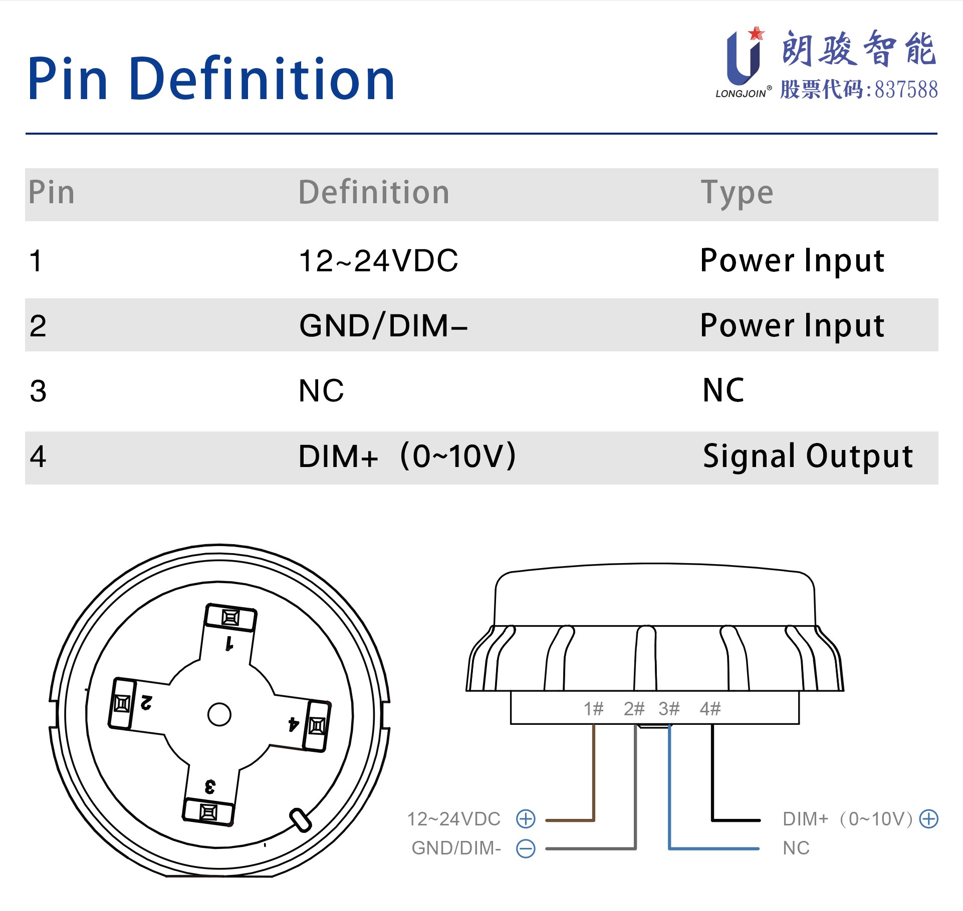
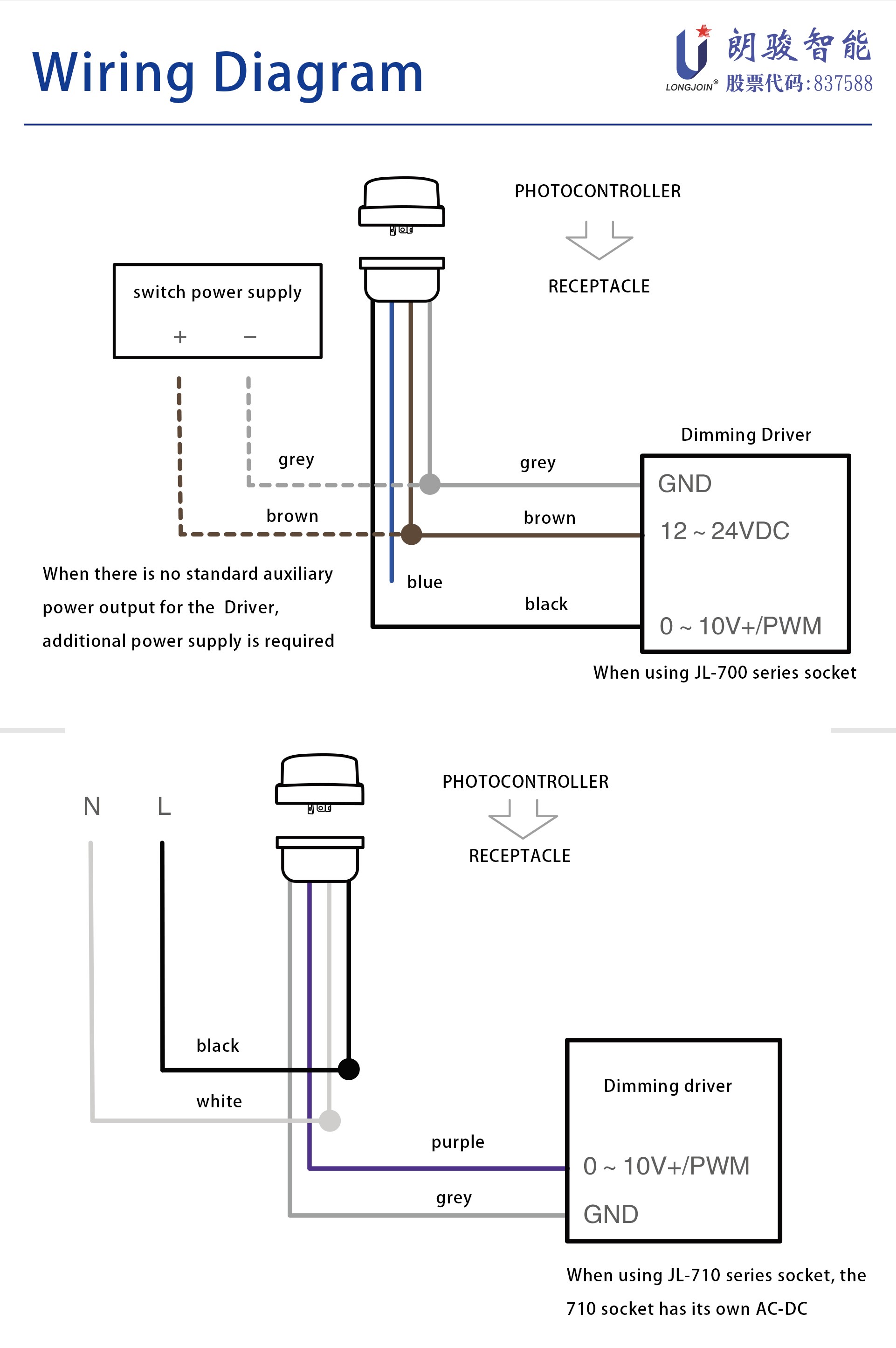
Wiring Diagram
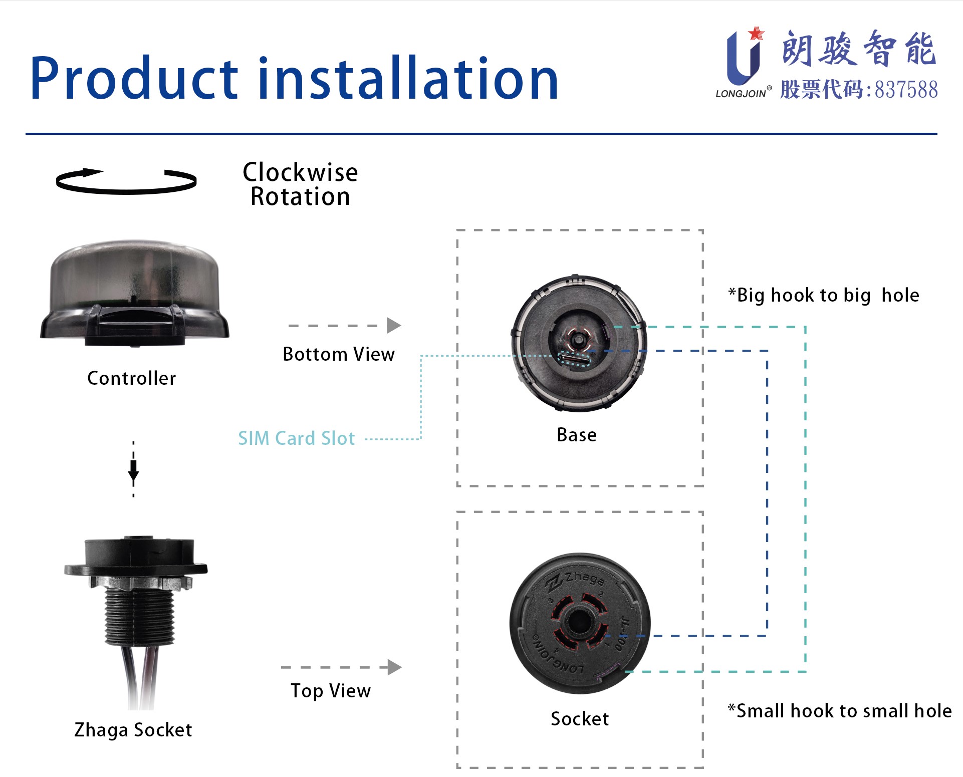
Product installation
The interface of the product itself has been protected against stupidity. When installing the controller, you only need to screw the controller directly with the base. As shown in the figure below, tighten it clockwise after insertion, and loosen it counterclockwise during removal.

Notice
1. If the negative pole of the auxiliary power supply of the driver is separated from the negative pole of the dimming interface, they need to be short circuited and connected to the controller #2.
2. If the controller is installed very close to the light source surface of the lamp, and the power of the lamp is also relatively large, it may exceed the limit of reflected light compensation, causing the phenomenon of self illumination and self extinction.
3. Because the zhaga controller does not have the ability to cut off the AC power supply of the driver, customers need to choose a driver whose output current can be close to 0mA when using the zhaga controller, otherwise the lamp may not be completely turned off. For example, the output current curve in the driver specification book shows that the minimum output current is close to 0mA.
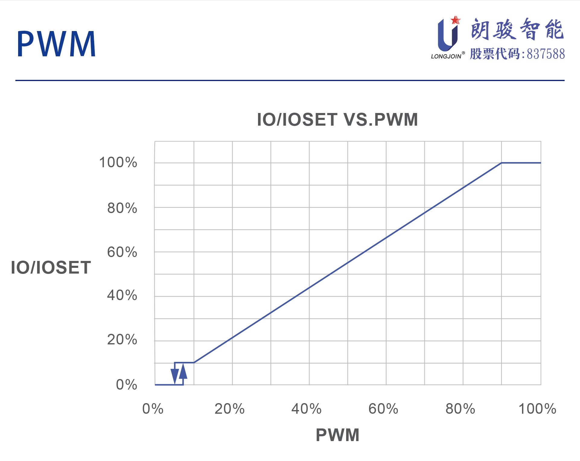
4. The controller only outputs the dimming signal to the driver, which is independent of the power load of the driver and light source.
5. Do not use your fingers to block the photosensitive window during the test, because the finger gap may transmit light and cause the light to fail to turn on.
6. Please leave the microwave module more than 1 meter away when testing the microwave. If it is too close, it may be filtered out as a false trigger, resulting in failure to trigger normally.